A 2mm PCD cutting tool blank outlasts 200+ carbide equivalents in aluminum machining. The catch? Most shops pick the wrong grade. They default to carbide when facing high-silicon aluminum or CFRP composites, burning through inserts and watching cost-per-part spiral upward.
Do the math: PCD achieves 50–250x longer tool life than carbide in non-ferrous applications. Cutting speeds reach 2,500 m/min – five times carbide. That’s up to 7x lower cost per part in mass production. The bottleneck isn’t the material – it’s knowing how to specify the right PCD cutting tool blank, find a reliable supplier, and validate quality before committing to volume.
This guide covers exactly that: how PCD blanks are classified, how grain size maps to your workpiece material, what quality indicators separate reliable suppliers from risky ones, and why a no-MOQ sourcing policy changes how you develop new tooling.
What Is a PCD Cutting Tool Blank?
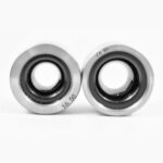
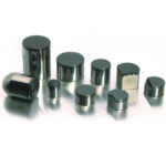
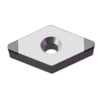
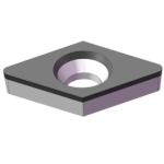
A PCD cutting tool blank is a two-layer composite disc: a polycrystalline diamond (PCD) layer bonded to a cemented tungsten carbide substrate under high-pressure, high-temperature (HPHT) sintering – pressures above 5 GPa, temperatures exceeding 1,400 °C. The diamond particles fuse with a metallic binder (usually cobalt) into a dense, ultra-hard layer anchored directly to the carbide backing. Also known as a polycrystalline diamond blank, this composite gives you the extreme hardness of diamond on the cutting face combined with the toughness and brazeability of carbide on the back. This HPHT process was pioneered by Element Six (a De Beers subsidiary) in the 1970s and has since become the global standard for polycrystalline diamond production.
That carbide substrate is what makes the blank useful: it allows EDM wire cutting, laser profiling, and high-temperature brazing onto steel tool bodies – none of which would work with unsupported diamond alone. The same HPHT sintering process also produces PCD wire drawing dies for metal wire manufacturing.
Key components:
- PCD layer (0.2–1.5 mm): Sintered diamond with metallic binder, providing cutting hardness of 7,500–10,000 HV
- Carbide substrate (1.5–3.2 mm): Tungsten carbide backing for structural support and brazeability
- Bond interface: Metallurgical bond verified by ultrasonic C-SCAN inspection
Why “blank” and not “insert”? The blank is the upstream raw material – a disc, wafer, or pre-cut shape that a tool manufacturer will process into a finished cutting geometry. It hasn’t been shaped into a specific rake angle, clearance angle, or chip-breaker profile yet.
PCD Blank vs. PCD Insert: What’s the Difference?
A PCD cutting tool blank is the unprocessed raw disc; a finished PCD insert is the ground, shaped, and brazed end product:
| Feature | PCD Cutting Tool Blank | Finished PCD Insert |
|---|---|---|
| Form | Disc, wafer, or near-net-shape preform | Ground/EDM-cut to final geometry |
| Customization | Full – any shape via EDM or laser | Fixed geometry per catalog |
| Lead time | Days from a responsive supplier | Days to weeks for special grades |
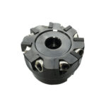
The path from blank to finished tool runs through EDM wire cutting (complex 2D profiles), laser cutting (faster, no electrode wear), or brazing (PCD tip soldered onto steel shank at ~800 °C with silver alloy) – often all three in combination.
PCD Blank Grain Size Guide: How to Choose the Right Grade
PCD blank grain size ranges from 1 μm (ultra-fine, maximum hardness) to 25 μm (coarse, maximum toughness). The correct grain size depends on your workpiece material’s abrasiveness and the required surface finish. Finer grains produce a harder, more wear-resistant edge; coarser grains sacrifice some hardness for toughness, surviving interrupted cuts and abrasive materials that would chip a fine-grain edge.
In our experience at Uking Diamond, the most common grain-size mistake we see is over-specifying fine grain for applications that involve interrupted cuts or abrasive inclusions – the edge chips within hours, and the shop blames the blank rather than the grade selection.
- Ultra-Fine (1–2 μm): Maximum hardness and best surface finish. Used for optical components, jewelry, and precious metals where Ra < 0.1 μm is required. Avoid interrupted cuts.
- Fine (5 μm): Strong balance of hardness and edge retention. Right for low-silicon aluminum (<12% Si), copper alloys, and brass.
- Medium (10 μm): The most versatile grade. Handles high-silicon aluminum (A380, A356), magnesium alloys, and green ceramics. Ideal first-specification grade.
- Coarse (25 μm+): Maximum toughness. Selected for A390 hypereutectic aluminum, CFRP/GFRP composites, and highly abrasive filled polymers.
Mixed-grain grades (e.g., 5+25 μm bimodal) trade peak hardness for improved fracture resistance in semi-interrupted conditions – recent HPHT sintering research confirms that bimodal distributions achieve higher structural integrity through improved particle packing density.
Quick Selection Table: Match Your Material to the Right PCD Grade
| Workpiece Material | Recommended Grain Size | Typical Application |
|---|---|---|
| Precious metals, optical Al | Ultra-Fine (1–2 μm) | Jewelry, optical component turning |
| Low-Si aluminum (<12% Si), brass, Cu | Fine (5 μm) | Engine covers, heat exchangers, connectors |
| High-Si aluminum (A356, A380) | Medium (10 μm) | Automotive cylinder blocks, wheels |
| Hypereutectic aluminum (A390) | Coarse (25 μm) | Engine pistons, transmission housings |
| CFRP / GFRP composites | Coarse (25 μm) | Aerospace structural panels, drone frames |
| MDF, HDF, laminated flooring | Medium–Coarse (10–25 μm) | Woodworking profile cutters, saws |
| PCB, FR4, fiberglass | Fine–Medium (5–10 μm) | Routing bits, drill blanks |
Not sure which grade fits your alloy? Request a free sample → and test before you commit to a bulk specification.
PCD Cutting Tool Blank Specifications: Shapes, Diameters, and Configurations
Understanding standard configurations helps you communicate precisely with your supplier – and avoids costly recuts when a blank arrives in the wrong geometry.
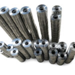
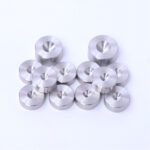
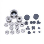
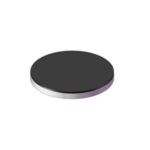
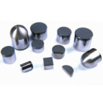
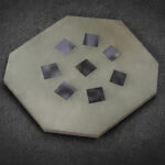
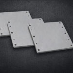
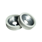
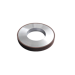
Round blanks (discs): The default format. Standard production diameters run Ø10 mm to Ø65 mm, with Ø41.3 mm, Ø52 mm, Ø58 mm, and Ø62 mm being the most common. Industry-standard sizes like Ø58 mm remain the most widely stocked globally across major PCD manufacturers. Used as-is for rotary tools or sliced into smaller tip blanks via EDM.
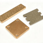
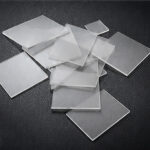
Pre-cut shapes: Many suppliers offer triangles, rectangles, trapezoids, and custom polygons cut from round blanks before shipment – saving in-house EDM time and reducing waste, especially for turning inserts and grooving tools.
PCD layer and carbide substrate thickness: PCD layer ranges from 0.2 to 1.5 mm; thicker layers (≥ 1.0 mm) suit deep-wear applications like high-speed wood routing, while thinner layers (0.2–0.5 mm) are economical for light-finishing. Carbide backing is typically 1.5–3.2 mm, determining brazing strength and thermal mass.
Custom configurations: Suppliers with in-house EDM and laser capabilities can produce near-net-shape blanks – pre-profiled to match a specific insert pocket geometry – minimizing your downstream processing time, especially for R&D teams iterating on new tool designs.
Key Industries and Applications for PCD Cutting Tool Blanks
Automotive – High-Silicon Aluminum Alloys (A390, A356)
Automotive powertrain components are increasingly cast from high-silicon aluminum for weight reduction. A390 (~17% silicon) is notoriously abrasive – a carbide tool machining an A390 piston bore may survive 500–800 parts; a correctly specified 25 μm coarse PCD blank extends that to 20,000+ parts. A Tier 1 supplier running a piston line at 1,200 parts/shift faces carbide tooling change-outs every 25–40 minutes. PCD? Tool changes measured in weeks.
Aerospace – CFRP and GFRP Composites
CFRP destroys carbide through rapid flank wear and fiber delamination. PCD’s thermal conductivity of up to 2,000 W/m·K – higher than copper – keeps cutting-edge temperatures low, preventing resin softening and fiber pull-out. (A property that also makes diamond heat sink materials invaluable for high-power electronics thermal management.) Standard aerospace spec: 25 μm grain with a sharp, positive rake geometry.
Woodworking – MDF, HDF, Laminated Flooring
Abrasive resins and alumina particles in MDF demolish HSS and carbide within hours. European flooring manufacturers routinely specify 10–25 μm PCD tips, achieving 6–12 months per tip set versus 2–3 weeks with carbide.
Electronics – PCB and Mobile Device Components
Fine-grain PCD (5–10 μm) produces the edge sharpness needed for < 0.2 mm PCB slot widths. Mobile device aluminum frames (6061-T6, 7075) benefit from 5–10 μm grades for cosmetic-quality surface finish.
How to Evaluate a PCD Blank Manufacturer: 5 Quality Indicators
When selecting a PCD blank manufacturer, skip any one of these checkpoints and you’re gambling on blank quality.
1. Ultrasonic C-SCAN Bonding Verification & Zero Delamination Guarantee
The bond between PCD layer and carbide substrate must be 100% defect-free – any void creates a stress concentration that fractures the blank during brazing or cutting. We’ve seen blanks pass visual inspection but fail C-SCAN – which is why at Uking Diamond we inspect every blank before shipment. Ask for the C-SCAN report, not just a certificate. And insist on a written zero-delamination warranty; suppliers who avoid that question are telling you something.
2. Grain Size Uniformity
A nominal “10 μm” grade should exhibit consistent grain size across the entire diamond layer. Ask for particle size distribution data (D50/D90 – median and 90th percentile particle sizes) alongside the standard grade specification.
3. Custom Geometry Capability (EDM and Laser)
A supplier with in-house EDM and laser can deliver near-net-shape blanks and iterate on non-standard geometries. Request a sample cut to your target geometry as part of qualification.
4. Technical Response Time
How fast the technical team responds to spec questions matters as much as lead time. A PCD blank supplier who answers grain size and substrate thickness questions in hours (not days) is one whose application knowledge can actually save you troubleshooting time.
Practical qualification step: Before placing any volume order, request a free sample batch matched to your exact specifications – testing on your actual cutting conditions is the only reliable way to validate a new supplier.
Why No-MOQ PCD Blank Sourcing Changes the Game for Tool Manufacturers
Marcus runs a 12-person cutting tool grinding shop in Stuttgart. His biggest growth constraint isn’t machining capacity – it’s the capital locked in PCD blank inventory. His previous supplier required a minimum order of 100 pieces per grade. For a shop running 8 different tool types across 4 grain sizes, that meant tying up €15,000–20,000 in blank stock just to maintain production flexibility. When he wanted to trial a new 2 μm ultra-fine grade for a jewelry client, the MOQ made the test economically unviable before a single cut was made.
Traditional PCD blank suppliers – including most established Chinese manufacturers – enforce MOQ policies ranging from 50 to 500+ pieces per specification. This structure works for high-volume OEM programs but directly penalizes:
- Small and mid-size tool grinders building custom tooling for niche applications
- R&D teams prototyping new geometries where grade selection is still being validated
- Distributors maintaining multi-grade inventory without the cash flow for large batch purchases
- Regrinding shops switching from a current supplier and needing to qualify a replacement
The MOQ barrier doesn’t just create financial friction – it kills experimentation. If testing a new grade requires a 200-piece commitment, many shops simply don’t test. They stay with a familiar (often suboptimal) specification because the sunk cost risk isn’t worth it.
How Zero-MOQ Sourcing Works With Uking Diamond
Uking Diamond operates on a no minimum order quantity policy: order a single blank, a dozen, or a full production run – pricing scales accordingly, but the order is never rejected for being too small.
The onboarding path runs four steps:
- Submit your specification – diameter, grain size, PCD layer thickness, substrate thickness, and geometry requirements
- Receive free samples – shipped matched to your spec, typically within 5-7 business days
- Test on your cutting conditions – run the samples on your actual workpiece material and tool body design
- Place your production order – only after sample performance meets your requirements
This is zero-risk onboarding: no upfront payment for the sample, no minimum volume commitment, and no obligation to continue if performance doesn’t satisfy.
For Marcus in Stuttgart, the model resolved his inventory lock-up problem. He now maintains a minimal buffer stock, orders weekly in the quantities he actually needs, and trials new grades without financial exposure. His inventory carrying cost dropped by ~60% in the first six months.
Ready to validate PCD blank quality before committing to volume? Request your free sample → – specify your grade, diameter, and application, and we’ll ship matched samples at no charge.
If you’re comparing PCD and carbide performance data to build the business case internally, the detailed analysis in our PCD vs. carbide for aluminum machining guide covers tooling economics across common aluminum alloy families.
Frequently Asked Questions
What is the standard diameter range for PCD cutting tool blanks?
Standard round PCD blank diameters typically range from Ø10 mm to Ø65 mm, with the most commonly stocked sizes at Ø41.3 mm, Ø52 mm, Ø58 mm, and Ø62 mm. Non-standard diameters are available on request from suppliers with flexible sintering and EDM capability.
Can PCD blanks be used for machining steel?
No. PCD reacts chemically with ferrous metals at cutting temperatures above ~700 °C – carbon in the diamond lattice diffuses into steel, destroying the cutting edge in minutes. PCD blanks are exclusively for non-ferrous materials: aluminum, copper, brass, magnesium, carbon fiber, glass fiber, and wood composites. For hardened steel or cast iron, PCBN blanks are the correct choice.
How are PCD blanks shaped into final cutting tools?
EDM wire cutting profiles the blank into 2D geometry; laser cutting handles fine geometries at higher speed; brazing bonds the PCD tip to a steel body at ~780–820 °C with silver-copper alloy filler. Post-braze grinding finishes the cutting edge to final tolerances.
What grain size PCD blank is best for aluminum machining?
It depends on silicon content. Low-silicon (<12% Si) – 6061, 2024: 5 μm fine grain. High-silicon (12–18% Si) – A356, A380: 10 μm medium grain. Hypereutectic (>18% Si) – A390: 25 μm coarse grain. When in doubt, start with 10 μm – the most forgiving all-around grade.
Do you offer samples before bulk ordering?
Yes. Uking Diamond ships free samples matched to your exact specification – grain size, diameter, PCD layer thickness – before any bulk order commitment. No MOQ on sample requests, no obligation to order afterward. Submit your specification via the inquiry form, WhatsApp, or email at [email protected]. Lead time: typically 5–7 business days.
Conclusion
You know the scenario: a PCD blank delaminates mid-run, and you’re 4,000 parts into a 10,000-part order. Or the grade chips on A390 because the grain size was off by 5 μm. Or you’ve got €15,000 in blank stock you may never use. These aren’t hypothetical – they’re the mistakes we see most often. And they’re all avoidable.
Get the grain size right for your workpiece material. Insist on documented C-SCAN bonding verification. And source from a PCD blank supplier whose MOQ policy lets you test before you commit.
Uking Diamond supplies PCD cutting tool blanks with no minimum order requirement and free sample testing – validate the exact grade, diameter, and layer thickness against your actual cutting conditions before placing any production volume.
Submit your specifications, request a free sample, or ask a technical question:
- Inquiry form: uking-diamond.com/product-category/pcd-cutting-tool-blanks/
- WhatsApp: +86-17192174537
- Email: [email protected]