Pick the wrong PCD blank grain size and your tool either chips on the first cut or leaves a surface finish that fails inspection. The difference between a 5 μm and a 25 μm blank isn’t incremental — it determines whether you’re delivering mirror finishes or scrapping workpieces. One midwestern tool shop learned this the hard way when they ran 5 μm PCD inserts against A390 high-silicon aluminum engine blocks. By shift two, every insert had chipped edges, and 340 parts sat in the reject bin. The fix was a single spec change — switching to 25 μm coarse-grade blanks — but the rework cost already exceeded $28,000.
That’s the stakes of PCD blank grain size selection. Get it right, and PCD delivers 50–250× longer tool life than carbide with cutting speeds up to 2,500 m/min. Get it wrong, and you’ve got premature failure, wasted material, and a production line standing still. This guide walks through every standard grain size, explains the trade-offs, and gives you a straight selection matrix so you can spec the right blank the first time.
Why PCD Blank Grain Size Is the Most Critical Specification
Every other property of your PCD cutting tool — edge sharpness, wear rate, impact resistance, even how fast your EDM wire can cut it — traces back to one variable: grain size.
PCD grain size — the average diamond particle diameter in a polycrystalline diamond blank — determines the balance between hardness and fracture toughness in every PCD cutting tool. Finer grains produce harder, denser PCD structures with lower fracture toughness. Coarser grains create a more open microstructure where diamond-to-diamond bridging distributes impact energy, giving you higher toughness at the cost of surface finish capability. It’s a hardness-versus-toughness trade-off, and there’s no way around it. Recent research on diamond particle size effects confirms that finer initial grain sizes produce higher abrasion resistance, while coarser grains deliver superior impact toughness (Zhang et al., Ceramics International, 2025).
Consider the numbers. PCD sits at 7,500–10,000 HV on the Vickers scale — roughly five to six times harder than tungsten carbide (1,500–1,800 HV). Polycrystalline diamond thermal conductivity reaches up to 2,000 W/m·K, which is why it dissipates cutting heat so effectively in high-speed non-ferrous machining (ScienceDirect: Polycrystalline Diamond). But these are bulk properties. Grain size is what determines whether that hardness translates into a sharp, stable cutting edge or an edge that micro-fractures under load.
Surface finish tells the story most clearly. A fine-grain (5 μm) PCD tool turning low-silicon aluminum can consistently achieve Ra (surface roughness average) values below 0.4 μm — functionally a mirror finish. Feed that same workpiece through a coarse-grain (25 μm) tool, and the inherent grain boundary steps push Ra above 1.2 μm, often unacceptable for cosmetic or precision surfaces. Research confirms the pattern: surface roughness increases with diamond particle size. A 2016 study by Tai and Nguyen found that 1.7 μm grain produced significantly smoother EDM-cut surfaces than 6 μm grain under identical parameters (Procedia CIRP).
Then there’s machinability of the blank itself. If you’re cutting PCD blanks by wire EDM or laser, coarse grain sizes slow you down. Each large diamond grain resists thermal erosion longer than a fine-grain cluster, meaning longer cutting times and higher electrode wear ratios. After EDM roughing, diamond grinding wheels bring the PCD cutting edge to final geometry tolerances. For tool manufacturers running high-volume EDM operations, grain size translates directly into per-tool production cost.
Grain size isn’t one of several specifications. It’s the specification that shapes every downstream decision. For a deeper dive into all PCD blank specifications — layer thickness, substrate, diameter — see our complete PCD cutting tool blank buyer’s guide.
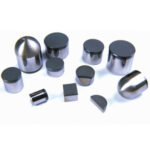
The 4 Standard PCD Blank Grain Sizes Explained
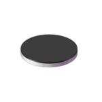
Ultra-Fine (1–2 μm) — For Mirror Finishes and Precious Metals
Ultra-fine PCD packs the smallest diamond grains into the densest possible structure. The result is maximum hardness and the smoothest possible cutting edge — essential when the workpiece surface is the product.
Where it excels: Precious metal machining (gold, silver, platinum), optical component turning, and mirror-grade aluminum finishing where Ra values below 0.2 μm are specified. Electrical contact components, watch cases, and decorative hardware are typical applications.
The trade-off: Ultra-fine grain gives you the best finish but the lowest fracture toughness. Any application involving interrupted cuts, hard inclusions, or significant silicon content will chip these edges quickly. EDM wire cutting works but at reduced speed compared to coarser grades, since the dense structure requires more discharge energy per unit volume.
Rule of thumb: If your customer inspects the part surface with a gloss meter rather than a caliper, ultra-fine is your grade.
Fine (5 μm) — For Low-Silicon Aluminum and Copper Alloys
Five-micron PCD hits the sweet spot where hardness and toughness overlap meaningfully — which is why it’s the most widely specified grain size in the industry. In our experience at Uking Diamond, 5 μm is the grade that 60–70% of our aluminum-cutting customers specify by default.
Low-silicon aluminum alloys (below 12% Si — A356, 6061, 3003), copper and brass turning, and general non-ferrous finishing all fall in this zone. Automotive trim components, heat sinks, electrical connectors, and bushings are the bread-and-butter applications for a PCD blank for aluminum with fine grain.
The limitation shows up once Si exceeds roughly 12%. Hard silicon particles in alloys like A356 or A380 act as micro-abrasives that gradually erode the cutting edge. For these borderline cases, 10 μm medium grain may be the safer bet — or a dual-grade approach if finish requirements are strict. If you’re unsure where to start with PCD grade selection, start with 5 μm.
Medium (10 μm) — The Universal Workhorse Grade
Ten-micron PCD is the “if you could only stock one grade” option. It doesn’t produce the finest finishes, and it doesn’t have the maximum abrasion resistance, but it does both well enough for the majority of non-ferrous applications.
Medium-silicon aluminum alloys, woodworking tooling (MDF, HDF, laminates, particleboard), and general non-ferrous milling and turning where surface finish requirements aren’t extreme — 10 μm handles them all. It’s also the go-to for mixed-material stack-ups where a single tool cuts through aluminum, adhesive, and steel in one pass, as commonly seen in automotive body-in-white assembly.
On pure low-silicon aluminum, 10 μm won’t match the finish of 5 μm. On high-silicon alloys or carbon-fiber-reinforced polymer (CFRP) composites, it won’t match the wear life of 25 μm. It’s a compromise — but an intelligent one when your production schedule includes varied workpiece materials and you can’t afford to change tools between every job. For smaller shops that serve diverse customers, 10 μm PCD blanks are a rational single-grade strategy.
Grain size drives cutting performance, but it’s not the only specification that matters. Several other blank parameters affect tool quality, cost, and production efficiency.
PCD layer thickness (0.2–1.5 mm). Thicker diamond layers allow more regrind cycles — a 1.0 mm layer can typically be reground 3–4 times versus 1–2 times for a 0.5 mm layer. However, thicker layers increase blank cost and can introduce residual stress that affects flatness. For disposable inserts, 0.5 mm is common; for regrindable tools, 1.0–1.5 mm pays for itself over the tool’s lifecycle.
Tungsten carbide substrate thickness. The WC base provides structural support and the braze interface for tool assembly. Thicker substrates improve welding strength and allow for taller tool geometries, but they also increase total blank cost and weight. Most standard polycrystalline diamond blanks use a substrate ratio of roughly 2:1 (carbide to diamond), but custom ratios are available for specific tool designs.
Surface condition (polished vs. unpolished). Polished PCD surfaces allow better visual inspection of the diamond layer and more consistent brazing, since surface flatness directly affects joint quality. Unpolished blanks cost less but require more careful preparation before welding.
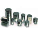
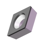
Blank diameter and yield. Larger-diameter blanks let you cut more inserts per disc, but the economics depend on your insert geometry. A 74 mm blank might yield 12 triangular inserts, while a 50 mm blank yields only 5 — but if your tool design uses 10 mm round inserts, the waste from the larger blank could make the smaller one more cost-effective. Match your blank diameter to your insert footprint.
For a full breakdown of PCD blank dimensions, tolerances, and ordering specifications, refer to our PCD cutting tool blank buyer’s guide.
Testing Before Committing to Bulk: Why Free Samples Matter
Even when the grade matches the workpiece on paper, shop-floor conditions rewrite the answer. Your coolant concentration is different from the reference. Your spindle runout is 2 μm instead of 0.5 μm. Your workpiece batch has slightly higher silicon content than the datasheet claims. Any of these variables can push a marginal grade choice from “works” to “fails.”
A Tier 1 automotive supplier in Germany ran into exactly this problem. They specified 10 μm PCD blanks for an A356 cylinder head finish operation based on the material’s nominal 7% silicon content. In production, the actual silicon content ranged from 7–11%, and at the upper end, tool life dropped 40% below their quoted cycle. The fix — switching to a 10/25 μm dual-layer blank — required three weeks of requalification. A single test run with sample blanks before the bulk order would have caught the variance on day one.
Small-batch testing isn’t optional. It’s the gap between theoretical selection and validated performance.
How Uking Diamond approaches this: We offer PCD cutting tool blanks with no minimum order and free sample testing. The process is straightforward. You specify the grain size, diameter, and layer thickness; we ship sample blanks at no charge. Run them under your actual production conditions, then confirm the spec before placing a volume order. No MOQ means you can start with exactly the quantity you need, whether that’s two blanks for a test or two hundred for a pilot run — zero-risk validation before you commit.
Want to test a PCD blank grade before committing to volume? Request your free sample and validate the grain size under real conditions.
Frequently Asked Questions
What is the most common PCD blank grain size for aluminum machining?
For low-silicon aluminum (<12% Si), use 5 μm PCD blank grain size. For high-silicon aluminum (>12% Si, e.g. A390), use 25 μm. For mixed applications, 10 μm is the compromise grade. Five-micron fine-grain PCD delivers surface finishes in the Ra 0.4–0.8 μm range while providing adequate wear resistance. Coarse-grain 25 μm PCD is standard for high-silicon alloys because the hard silicon particles require maximum abrasion resistance. If you’re running both low- and high-Si alloys on the same line, 10 μm is your path of least resistance — you’ll sacrifice some finish on the low-Si parts but avoid catastrophic edge failure on the high-Si ones.
Can I use a coarse-grain PCD blank for fine finishing?
Technically yes, but the results will disappoint. Coarse-grain (25 μm+) PCD leaves inherent grain-boundary steps on the machined surface, typically producing Ra values of 1.0–1.6 μm. If your application requires Ra below 0.8 μm, coarse grain won’t get you there regardless of cutting parameters. For fine finishing, use 5 μm or finer grades and reserve coarse blanks for roughing or abrasive applications.
How does PCD grain size affect EDM cutting speed?
Coarser PCD grain sizes slow down wire EDM cutting. Each large diamond grain resists thermal erosion longer than fine-grain clusters, requiring more discharge events per unit length. A 2016 study found that under identical EDM parameters, 6 μm PCD achieves higher material removal rates than 1.7 μm PCD but at the cost of increased surface roughness on the cut edge. In practice, operators adjust by increasing current and pulse-on time for coarser grades, but electrode wear increases proportionally.
What grain size should I choose for woodworking tools?
10 μm medium-grain PCD is the standard for woodworking tools cutting MDF, HDF, particleboard, and laminates. These materials contain abrasive adhesive resins and hard glue joints that wear down fine-grain edges prematurely, but they don’t require the extreme toughness of 25 μm coarse grade. For solid wood or panel tools where surface quality on the cut edge matters, 10 μm provides the right balance of edge life and finish quality.
Do you offer PCD blank samples in different grain sizes?
Yes. Uking Diamond provides free sample blanks across all standard grain sizes — from 1–2 μm ultra-fine through 25 μm coarse — with no minimum order quantity. You can request multiple grades to run side-by-side comparisons under your production conditions before placing a volume order. Contact us via the website form, WhatsApp, or email [email protected].
Choose the Right Grain, Test It, Then Scale
Three things determine whether your PCD blank grain size selection works or doesn’t: match grain size to workpiece abrasiveness first (fine for clean metals, coarse for abrasive composites), account for surface finish requirements second (finer grain = smoother finish), and validate under real conditions third (theoretical selection is not a substitute for test cuts).
Ready to stop guessing and start testing? Uking Diamond ships free sample PCD blanks in any grain size — no MOQ, no risk. Specify your grade and diameter, and we’ll send one for your validation run. Reach us through the website form, WhatsApp, or [email protected].